概要
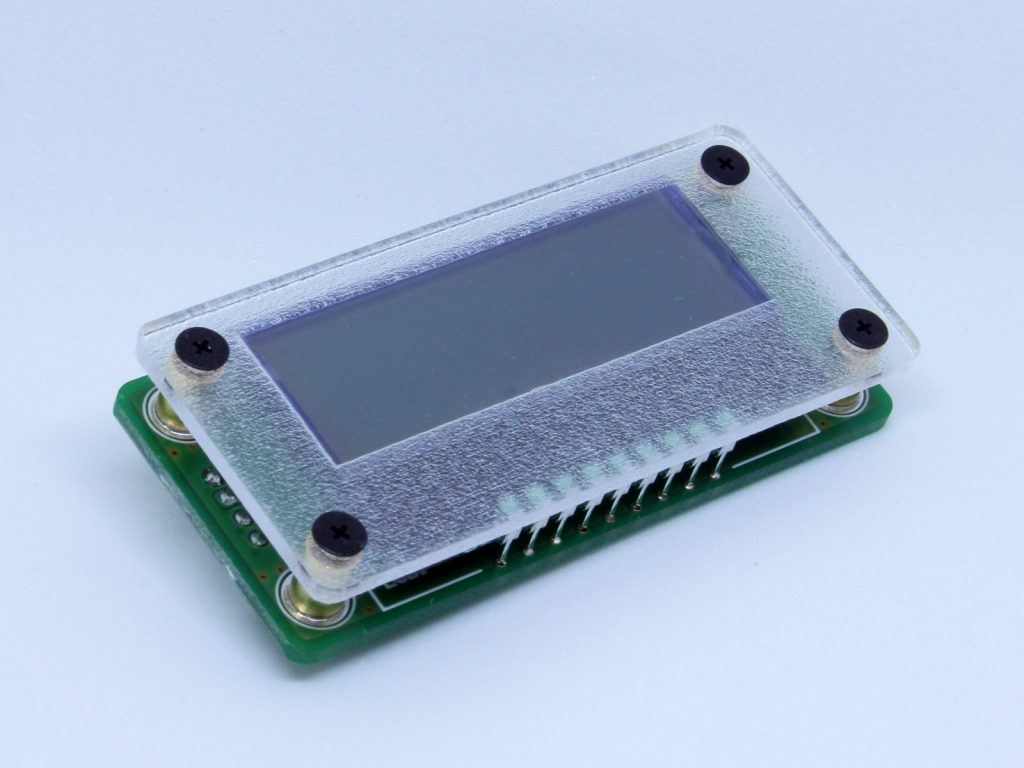
本製品は、ホスト側の電源電圧とIO電圧が1.8V~5.0Vまで広範囲に対応した、I2C接続の16桁x2行のキャラクタLCDです。
Rev1.1は、Rev1の改修版のバージョンとなります。
Rev.1 をご購入の方へ
Rev.1には動作が不安定、または動作しない不具合があります、以下の対応をご参照ください。
仕様
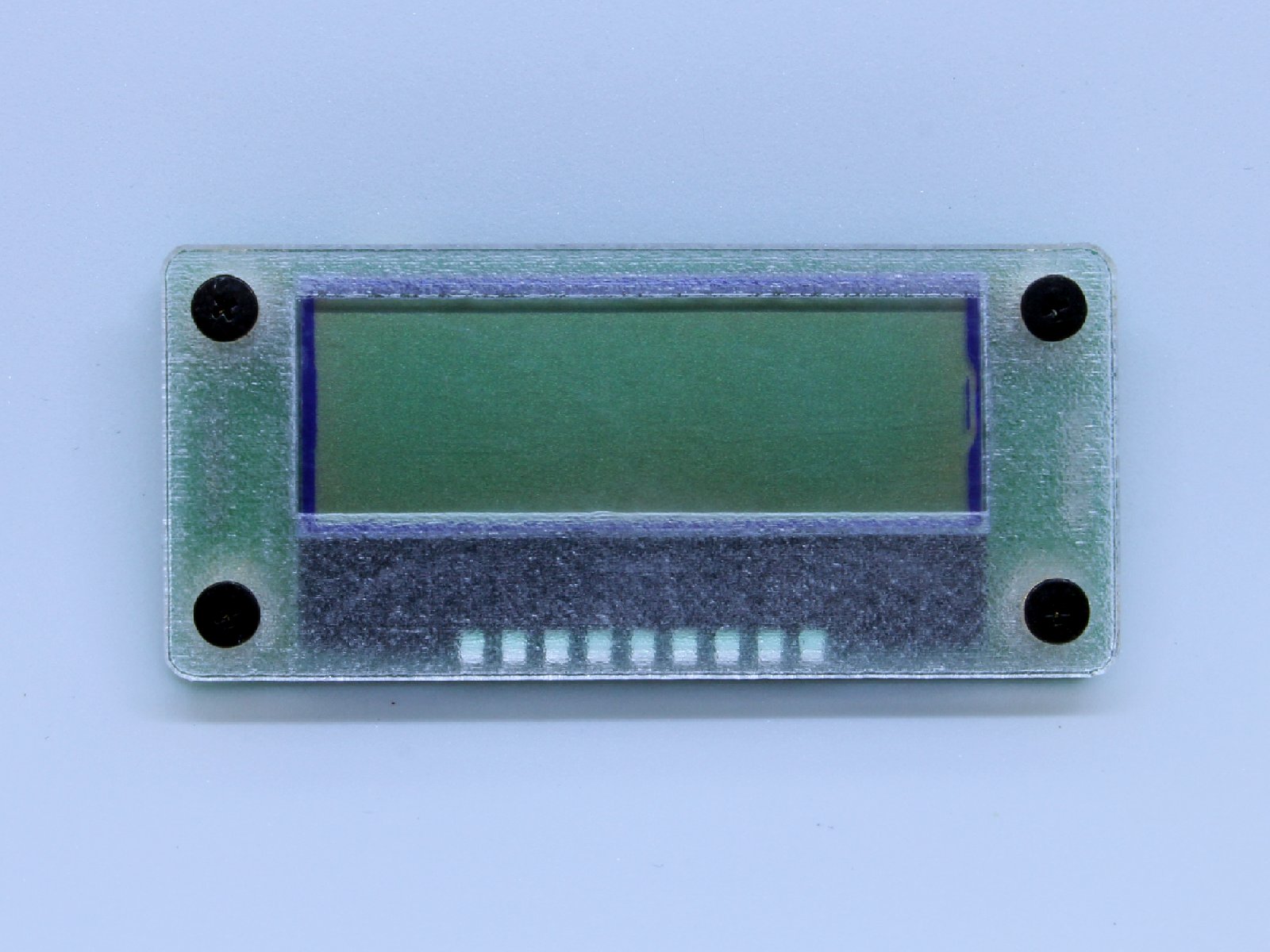
- アクリルフロントパネル付きでLCDを衝撃から保護します。
- M2スペーサナットは基板と固定されているので、フロントパネルを外し自作のケース等に簡単に取り付けることができます。
- 5V系統のArduino、3.3V系統のRaspberry Pi、1.8V系統のSpresenseなどの接続時、電圧レベルを気にすることなく使用できます。
- LCD部品の保護シートは剥がさずそのまま出荷しています。シートを剥がす場合は一度フロントパネルを取り外して頂く必要があります。
- 入力電源電圧、入力IO電圧:1.8V~5.0Vに対応
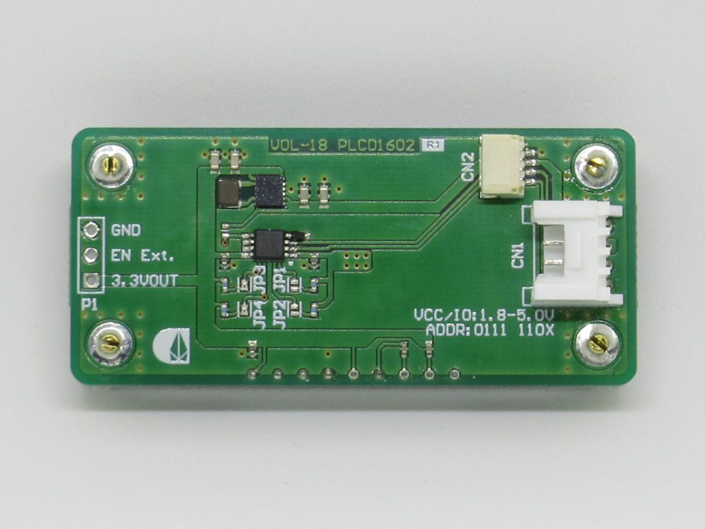
- 接続:Qwiicピン互換I2C接続、またはGroveピン互換I2C接続
- LCD:16桁x2行のキャラクタLCD (秋月電子通商 AQM1602Y-RN-GBW)
- I2Cアドレス:0111 110x
- 3.3V電源出力端子付き(回路図参照 P1端子)
内容物
- PLCD1602 1台
(コネクタ接続用ケーブルは付属しません)
資料
- 回路図(Rev1) 【廃版】
- 回路図(Rev1.1)
- 寸法参考図(DXF)
- 3D参考図(STEP)
(都合により3D図はLCDの高さが低くなっています。製品では基板から約2mm浮いています。) - 使用例
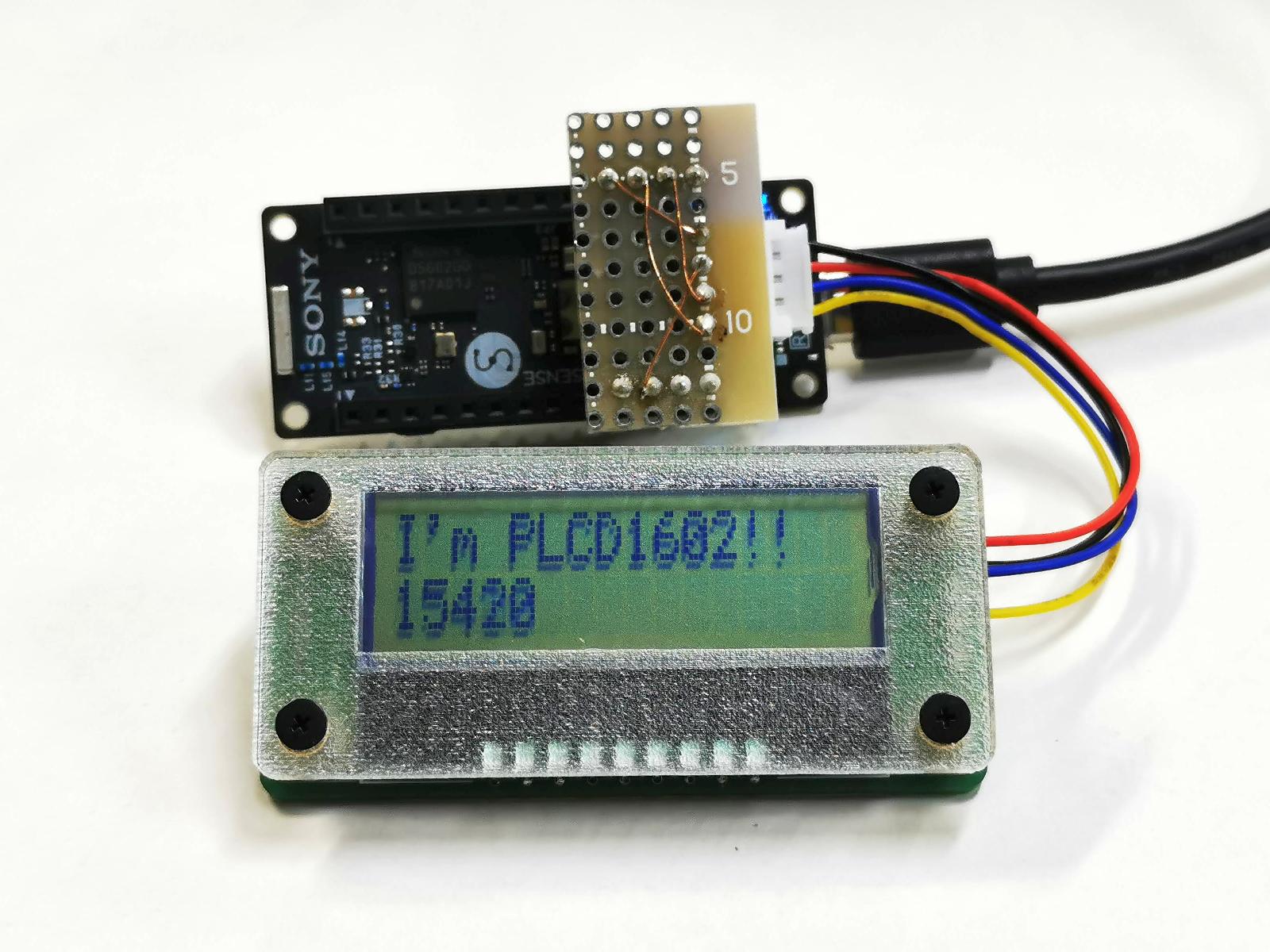
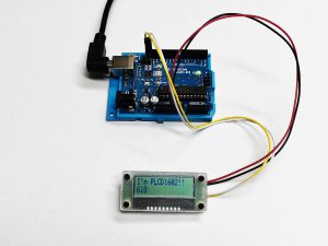
- サンプルコード
/*
  Title : [VOL-18]PLCD1602 sample code
  Copyright : Copyright (c) 2021 Crane-elec. Co., LTD.
  URL : https://crane-elec.co.jp/products/vol-18/
  License : Released under the MIT license
*/
#include <Wire.h>

/* for Arduino UNO */
#if defined(__AVR_ATmega328P__)
#define LED0 (13)
#endif

//-----------------------------------------
//PLCD1602 functions
#define PLCD_ADDR (0x3E)

void plcd_cmd(char d)
{
  Wire.beginTransmission(PLCD_ADDR);
  Wire.write(0x00);
  Wire.write(d);
  Wire.endTransmission();
}
void plcd_data(char d)
{
  Wire.beginTransmission(PLCD_ADDR);
  Wire.write(0x40);
  Wire.write(d);
  Wire.endTransmission();
}
void plcd_cgram(char adr, char *d, int len)
{
  Wire.beginTransmission(PLCD_ADDR);
  Wire.write(0x00);
  Wire.write(0x40 | (adr * 8));
  Wire.endTransmission();
  for (int i = 0; i < len - 1; i++)
  {
    Wire.beginTransmission(PLCD_ADDR);
    Wire.write(0xc0);
    Wire.write(*d);
    Wire.endTransmission();
    d++;
  }
  Wire.beginTransmission(PLCD_ADDR);
  Wire.write(0x40);
  Wire.write(*d);
  Wire.endTransmission();
}
//-----------------------------------------

void setup() {
  pinMode(LED0, OUTPUT);
  Wire.begin();
  Wire.setClock(100000L);

  //PLCD init.
  delay(40);
  plcd_cmd(0x38);
  plcd_cmd(0x39);
  plcd_cmd(0x04);// EntryModeSet
  plcd_cmd(0x14);
  plcd_cmd(0x70);
  plcd_cmd(0x56);
  plcd_cmd(0x6c);
  delay(200);
  plcd_cmd(0x38);
  plcd_cmd(0x0c);
  plcd_cmd(0x01);
  delay(3);//Clear Display interval

  //setup CGRAM
  char cg0[8] = {0x04, 0x04, 0x04, 0x1f, 0x00, 0x0e, 0x00, 0x04};
  char cg1[8] = {0x1f, 0x1f, 0x1f, 0x1f, 0x11, 0x11, 0x11, 0x1f};
  char cg2[8] = {0x1f, 0x11, 0x11, 0x11, 0x1f, 0x1f, 0x1f, 0x1f};
  char cg3[8] = {0x04, 0x04, 0x15, 0x0e, 0x04, 0x00, 0x1f, 0x1f};
  char cg4[8] = {0x1f, 0x10, 0x10, 0x10, 0x10, 0x10, 0x10, 0x1f};
  char cg5[8] = {0x1e, 0x02, 0x02, 0x03, 0x03, 0x02, 0x02, 0x1e};
  char cg6[8] = {0x1f, 0x11, 0x0a, 0x04, 0x04, 0x04, 0x04, 0x04};
  char cg7[8] = {0x01, 0x01, 0x05, 0x05, 0x15, 0x15, 0x00, 0x1f};
  plcd_cgram(0, cg0, 8);
  plcd_cgram(1, cg1, 8);
  plcd_cgram(2, cg2, 8);
  plcd_cgram(3, cg3, 8);
  plcd_cgram(4, cg4, 8);
  plcd_cgram(5, cg5, 8);
  plcd_cgram(6, cg6, 8);
  plcd_cgram(7, cg7, 8);

  //
  plcd_cmd(0x80 | 0); //Set Cursor (0,0)
  for (int i = 0; i < 8; i++) {
    plcd_data(i);
    plcd_data(' ');
  }
  //
  plcd_cmd(0x80 | 0x40);//Set Cursor (0,1)
  for (int i = 0; i < 8; i++) {
    plcd_data('0' + i);
    plcd_data('-');
  }

}

void loop()
{
  digitalWrite(LED0, HIGH);
  delay(100);
  digitalWrite(LED0, LOW);
  delay(100);

  for (int lp = 0; lp < 256; lp++)
  {
    plcd_cmd(0x80 | 0x4f);//Set Cursor (15,1)
    plcd_data(lp);
    delay(100);
  }
}
- 製品写真
動作確認済みライブラリ
ArduinoIDEのライブラリ管理からインストールでき、当社がArduino UNO R3で独自に動作確認をしたライブラリです。
ライブラリ作者に本製品についてのお問い合わせはお控えください。
- ST7032_asukiaaa https://github.com/asukiaaa/ST7032_asukiaaa (ライセンス:MIT)
- LCD_ST7032 https://github.com/olkal/LCD_ST7032 (ライセンス:MIT)
- FaBo 213 LCD mini AQM0802A https://github.com/FaBoPlatform/FaBoLCDmini-AQM0802A-Library (ライセンス:Apache-2.0 License)
販売
- 供給
終了予定なし(2022/09現在)
付記
本文中に記載されているArduino、Raspberry Pi、Spresense等は、各社の登録商標または商標です。

